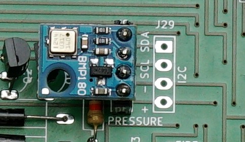
The Riki board is complex, and contains quite a lot of different chips that should not be soldered directly onto the board, but connected through female pin headers or DIP sockets.
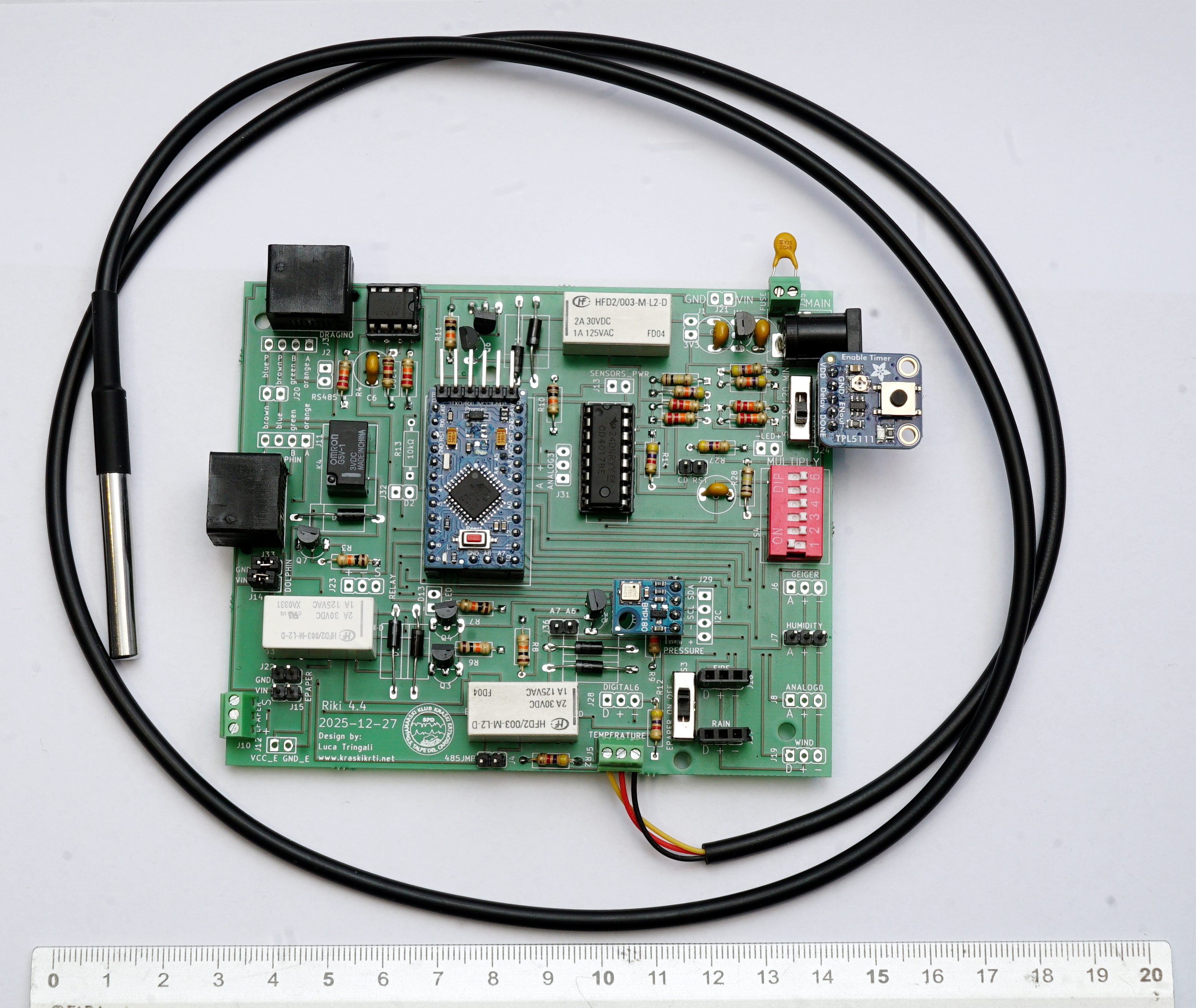
These chips are:
- Arduino Pro Mini 3.3V
- TPL5111
- CD4017
- MAX3485
- BMP180 (optional)
Also, it's important to note that the Riki board has two pins for a fuse: specifically, it's recommended to use a pptc resettable fuse for 0.25 Ampere, in order to protect both the battery and the MCP1702 voltage converter. This fuse could be soldered directly onto the board, but we highly recommend using a screw terminal (2.54mm female headers are usually too large for these fuses): this way, if the fuse gets damaged, it's possible to just replace it, without having to replace the board itself (and withotu desoldering).
Preparing Arduino
To prepare the Arduino board, please follow these instructions.
Preparing the timer
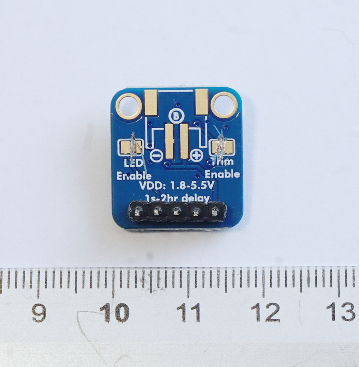
To prepare the TPL5111 timer, it's just necessary to cut the two contacts called LED enable and Trim Enable: the device is designed to let you do this with a cutter. Then, it's necessary to solder pin headers on the bottom side.
Soldering components on the board
Power
Riki should get power from a 12V battery: usually, they are provided with a standard 2.1x55mm DC plug, so Riki is designed for a DC socket.
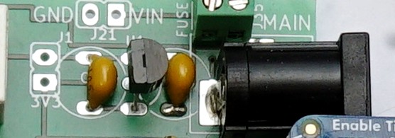
If, for some reason, it's not possible to use a DC plug, there are also two contacts for 2.54mm screw terminals, so it's possible to connect any kind of battery. The MCP1702 voltage regulator can be soldered directly onto the board, but it's important to follow the same direction as the shape drawn on the board. After the last of the two 1uF ceramic capacitors required by the regulator, there are two contacts for 3.3V and GND, that can be use to power anything that requires to be on at all time. For example, it could be a sensor that counts events (e.g.: a bat detector) even when Arduino is asleep.
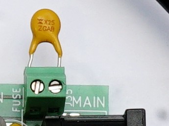
The Riki board should be protected by a fuse, to avoid burning chips or overheating the battery if there's a short circuit somewhere. We suggest soldering a screw terminal on the board and connecting a PPTC fuse to it. If you decide to not use a fuse, you can just solder two pin headers and short circuit them using a jumper.
The timer contacts should be setup with pin sockets, so that they fit the timer's pins headers. A standard 3-way switch should be soldered to let the user easily choose between 5, 30 or 120 minutes of sleep. The DIP switch for the multiplying factor must be soldered with th "6" side closer to the timer. The multiplying factor works like this: if you've choose 120 minutes, and a multiplying factor of 3, the board is going to sleep for 360 minutes (6 hours).
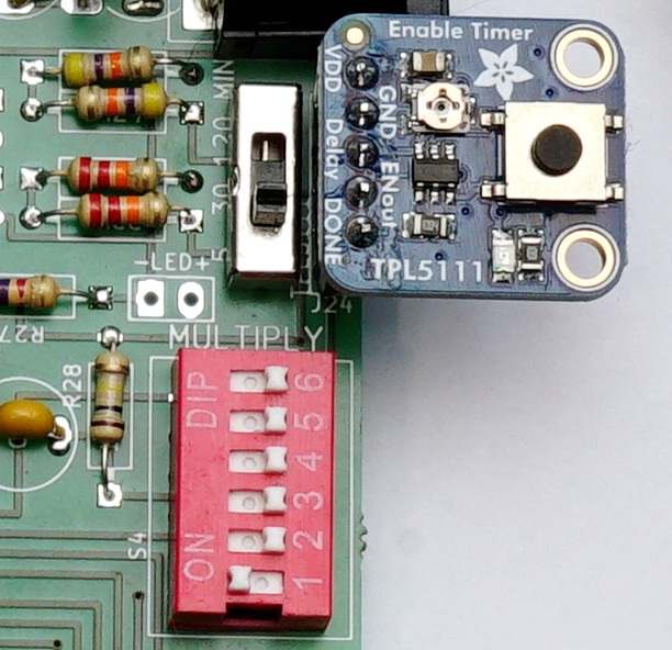
If you don't need a multiplying factor, and don't want the decade counter to interfere, you can just short circuit the first two contacts of the DIP switch, so it's possible to avoid it entirely.
The decade counter should not be soldered directly on the board, but instead with a DIP socket, so it's easy to remove it if it is not encessary. It's actually possible to just not sodler it, if you don't need a multiplying factor and are fine with just the 5-30-120 minutes sleep options.
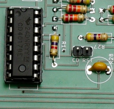
The CDRST jumper can be used while testing Riki to just periodically reset the decade counter and avoid it missing some impulses from the timer. If you don't plan on experimenting with the decade counter, you don't need to solder these pins.
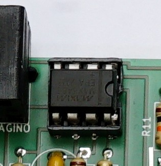
The MAX3485 should not be soldered directly onto the board, instead it should be mounted on a DIP socket, so it's easier to remove it. This is important because, in case of a short circuit, the MAX chip on Riki is usually the first component to burn. If it can be easily removed and replaced, the Riki board might resume working without requiring additional maintenance.
Connections
Riki needs to be connected both to Dolphin and Dragino: this can be done using RJ45 sockets. Right next to each RJ45 mount, there are also 4 pins for screw terminals, so it's possible to use simpler wires. If using screw terminals, the RJ45 holes can be used to fix the wires to the board with a zip tie, to avoid them breaking when Riki is moved around.
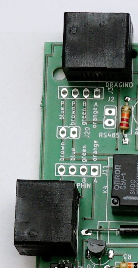
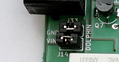
The Dolphin board receives power from Riki thanks to a dedicated relay. The power can come from the same 12V battery powering Riki, or another one if you want to completely separate the two power sources. If you want to use the same battery, just use jumpers to connect the dolphin VIN and GND. If you want to use a different power source, just solder a screw terminal on the two pins near the "DOLPHIN" text on the board (not the VIN and GND text). This will allow you to connect a battery only to Dolphin.
Relays
Riki uses 3 latching relays:
- to power on Arduino and start one data collection cycle
- to power on Dolphin
- to (optionally) power on the ePaper module and switch the tx hardware serial
Relay #1 gets switched on by the TPL5111 timer impulse, and gets turned down by Arduino itself. When this is on, power is provided to the SENSORS_PWR* pins and every analog or digital set of pin.
Relay #2 gets switched on by Arduino, and gets powered off immediately as soon as a valid Dolphin message has been received.
Relay #3 gets powered on by Arduino, and gets powered off after a fixed delay time (which has been calculated to be enough to let the eInk redraw the screen). This relay switches both the ePaper power and the serial tx line, because the serial line would interfere with RS485.
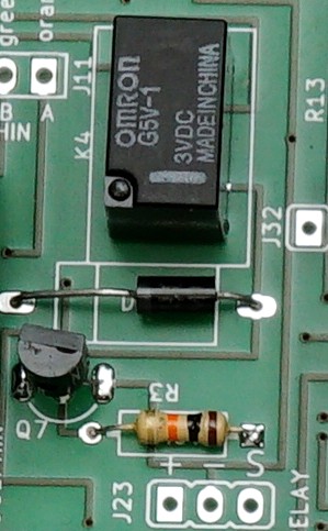
Each relay needs two 10kOhm resistors, two 1N4001 diodes, and two 2N2222 transistors. The correct side for mounting transistors and diodes is drawn on the board. The relays have a layout that is not symmetrical.
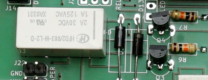
There is another, simple, relay, used to trigger Dragino to send data through LoRaWAN. This relay also needs one 10kOhm resistor, one 1N4001 diode, and one 2N2222 transistor.
ePaper-sdcard logger
The ePaper/datalogger module can be connected to Riki using a 3-way screw terminal:
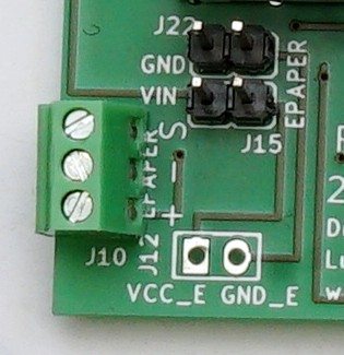
It has the same mechanism already described for powering Dolphin: if you want to power it on the same 12V battery used by Riki, you can just opt for two jumpers to connect the pins. Otherwise, you can mount screw terminals on the "EPAPER" end of the pins and just connet the other battery there.
The ePpaper makes the Riki run time much longer, so if you don't really need it, it's a good idea di turn off the ePaper function. This can be done using a switch. To make things easier, we've designed the board to have here the same 3 way switch already used for selecting the sleep interval: this way you can just buy two of the same component.
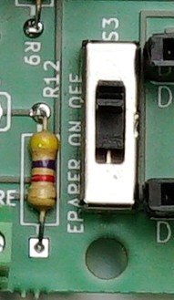
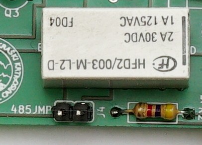
If you really do not care about the ePaper/datalogger and do not want to waste time on soldering, it's also possible to completely avoid soldering all the ePaper related components (jumpers, terminals, switch, relay and its resistors, diodes and transistors). If you don't solder the relay, it's important to at least solder the 485JMP jumper. This jumper bypasses the relay, and lets the MAX485 module use the serial tx line. If the 485JMP is not short circuited, Riki will not be able to communicate with Dolphin and Dragino with RS485.
Sensors
The Riki board should always have at least the DS18B20 thermometer: just as on Dolphin, the board is designed for the 3-way screw terminal and the 4.7kOhm resistor required by this sensor.
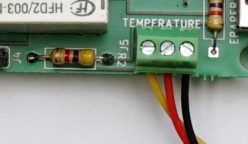
Riki also has a number of analog and digital pins available for sensors, but there are also two pin sets designed for pin sockets for I2C sensors. One of these can be used for measuring pressure with a BMP180 sensor, and the other one is available for any other sensor.