The Dolphin board is quite simple in itself, but it needs some work to be enclosed in a waterproof container (if desired).
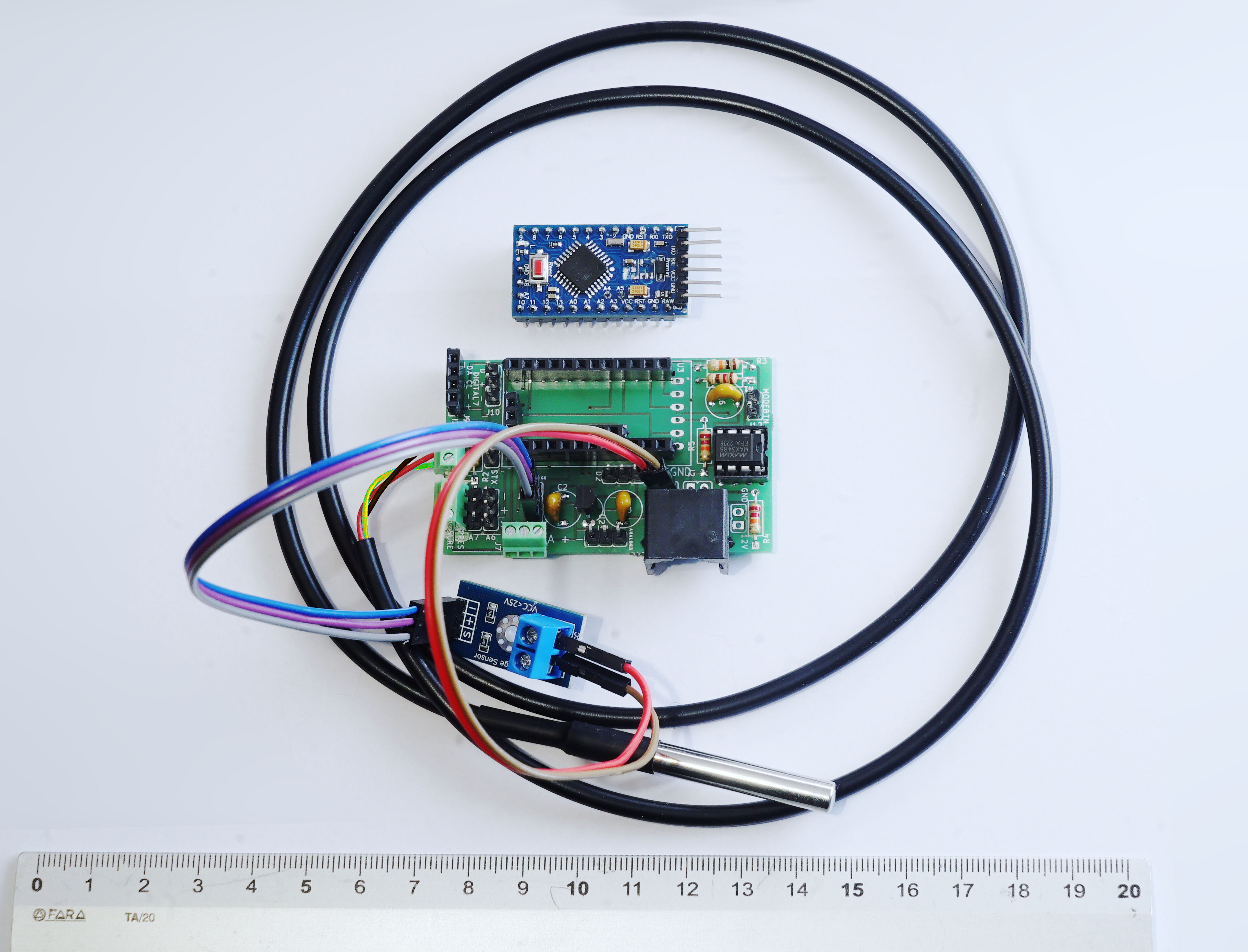
Not all connectors actually need to be soldered: it's mandatory to have 2.54 female pin headers for Arduino Pro Mini, and the 8-DIP socket for the MAX3485 chip (to easily remove both components when necessary). Resistors, capacitors, and the MCP1702 chip should be solderes directly onto the board. Connectors for sensors can be soldered only if necessary: it's always recommended to have a DS18B20 thermometer (which can be connected sodlering a 3-way screw terminal to the board), but if you don't want (for example) to measure pressure, you can leave its connectors unsoldered.
Preparing Arduino
To prepare the Arduino board, please follow these instructions.
Soldering components on the board
First of all, it's a good idea to use pin sockets for the Arduino board, so it's easy to remove it when necessary. The FTDI side should not be soldered, because it needs to remain free. The A6-A7 pins can be soldered only if they are actually necessary.
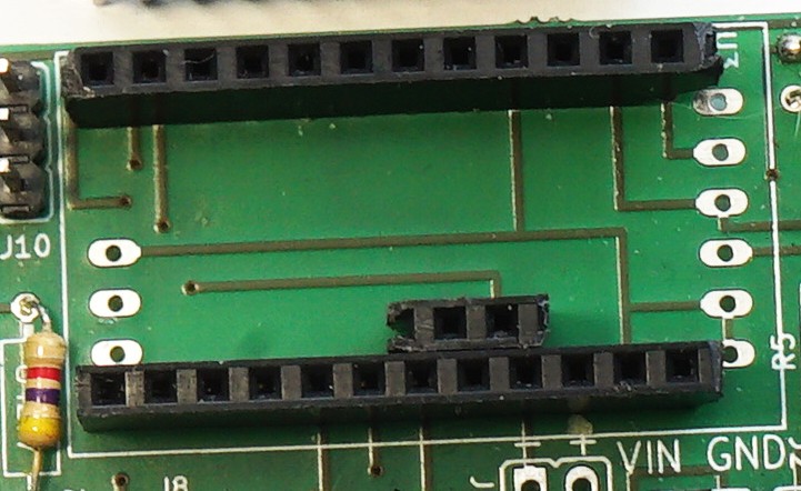
The MCP1702 voltage regulator (U2) must be soldered following the semicircle shape drawn on the board:.
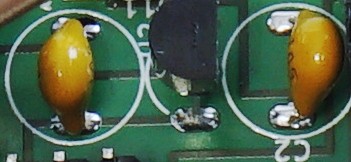
The two 1uF capacitors (C2, C3) are ceramic, and do not have a polarity.
The RJ45 connector is quite easy to mount, because its pins have a precise shape. The clips can be hard to insert in the holes, it might be necessary to press them hard. It's recommended to solder all pins, to improve stability, but only the first row is actually used.
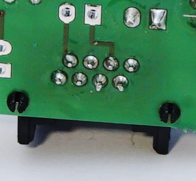
Right behind the RJ45 connector, there are two power input pins: these can be used for screw terminals if you've decided not to use the RJ45 connector (close to these, there are also pins for the RS485 lines, if not using the RJ45). Even if using the RJ45, the 12V and GND pins can be used to measure the voltage, connecting them to a Voltage Sensor.
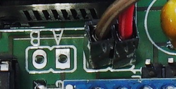
The Voltage Sensor data pins are labeled as "VOLTAGE":
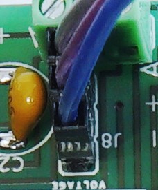
The Voltage Sensor has indeed three data pins (actually only one for analog data, two for 3.3V power) and two screw terminals for the 12V and GND that we need to measure:
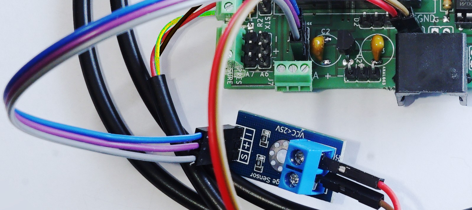
The Voltage Sensor is required, because the voltage reading is used by Riki to detect whether Dolphin data are valid.
It's necessary to solder a DIP-8 socket for the MAX3485 chip: if the chip is soldered directly onto the board it won't be possible to remove it during calibration of sensors. If the MAX3485 is connected, it's not possible to send data to Dolphin via serial connection.
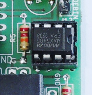
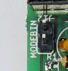
The calibration mode jumper, marked as MODEBTN, can be a pushbutton or just simply 2 pin headers. If the two contacts are short circuited while powering on Dolphin, the board will start in calibration mode.
Sensors
Dolphin supports a multitude of sensors. The bare minimum to make it work are the Voltage sensor and the Temperature sensor, but for underwater measurements it's also recommended to connect at least a Pressure sensor. These sensors are really cheap, and should be available to everyone: if your budget allows it, it's also a good idea to provide Dolphin with an Electrical conductivity probe:
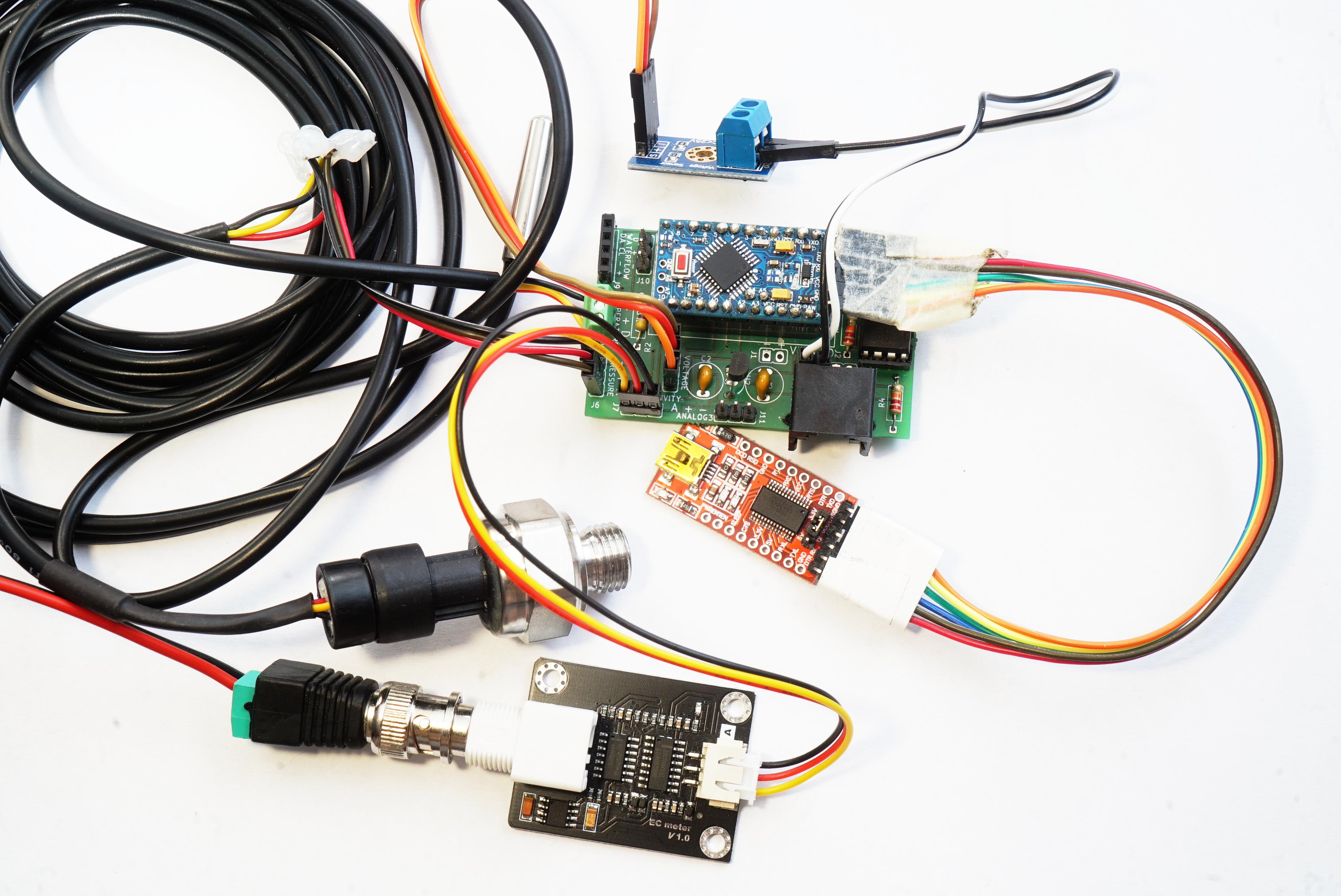
The board can be connected to a computer using an FTDI-USB adapter, directly connected to the Arduino FTDI pins.
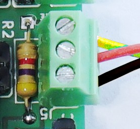
Dolphin should always have at least the DS18B20 thermometer: temperature is always a useful variable, no matter what other sensors will be connected. The Dolphin board should have the 4.7kOhm resistor (R2) required by the sensor, and then a 3-lines screw terminal to connect the sensor itself (which is usually sold with three cables):
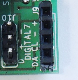
Dolphin also has a standard I2C bus, with 3.3V, GND, SDA and SCL lines: they can be soldered with pin sockets or screw terminals. This way it will be possible to connect I2C enable sensors, which usually are provided with standard pin headers.
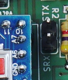
A serial connection (Rx/Tx lines) is provided through Software Serial (on Arduino pins 10-11, for rx and tx respectively).
Calibration
It's important to calibrate sensors, to make sure their readings are correct. Dolphin can start in calibration mode by short circuiting the MODEBTN pins (e.g.: with a jumper) and then powering up the board.
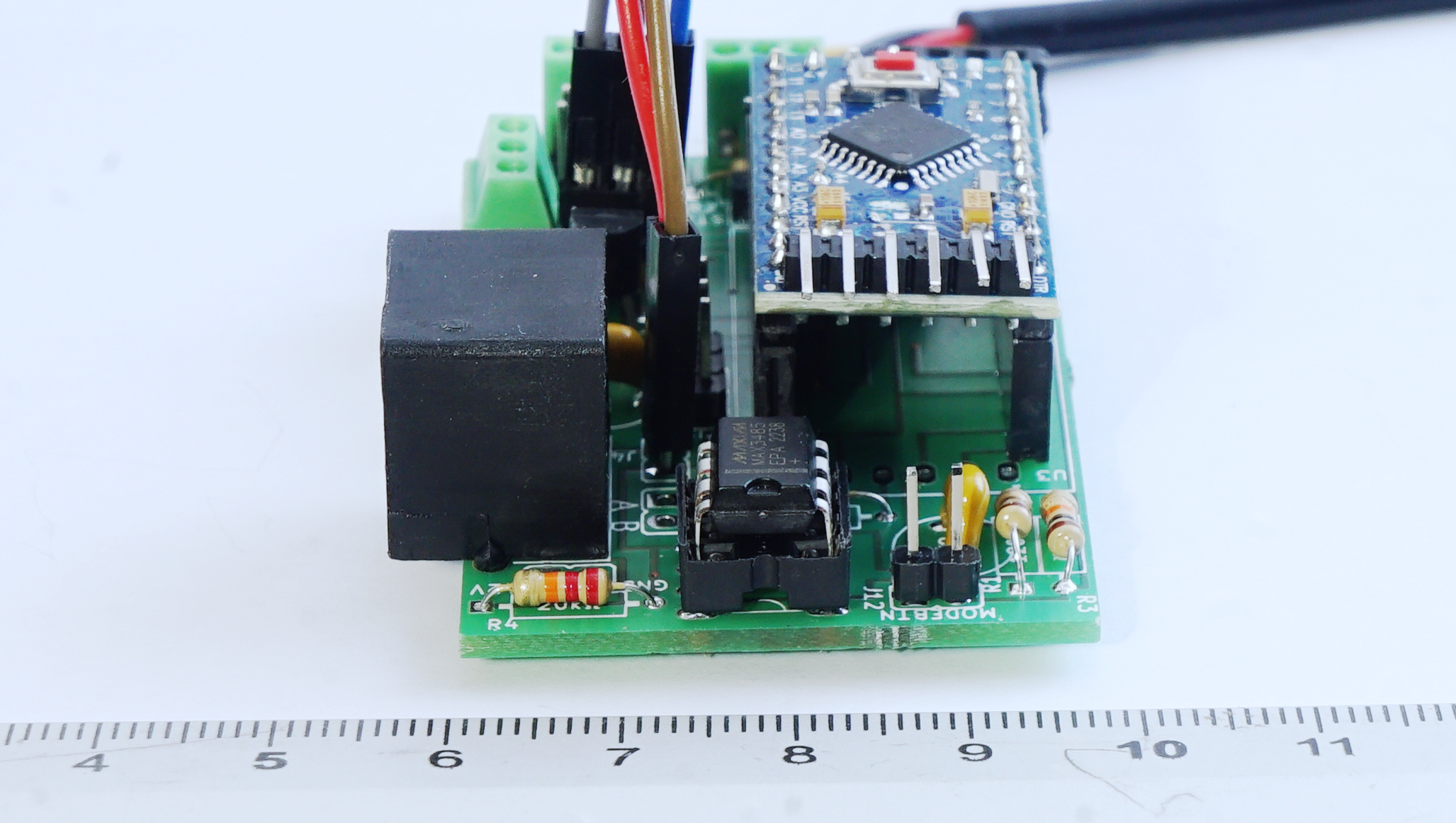
It's recommended to connect the board to a computer via a FTDI-USB adapter, open the serial terminal on the computer, then power the board with 12V from Riki (or power it through the FTDI adapter, if it provides 3.3V), short circuit the MODEBTN and then reset the board by pressing the Arduino reset button. This way, we're sure the voltage running the board is the same 3.3V that will be powering it in the cave. This is important because some FTDI adapters power the board using 5V, and that would cause wrong pressure readings.
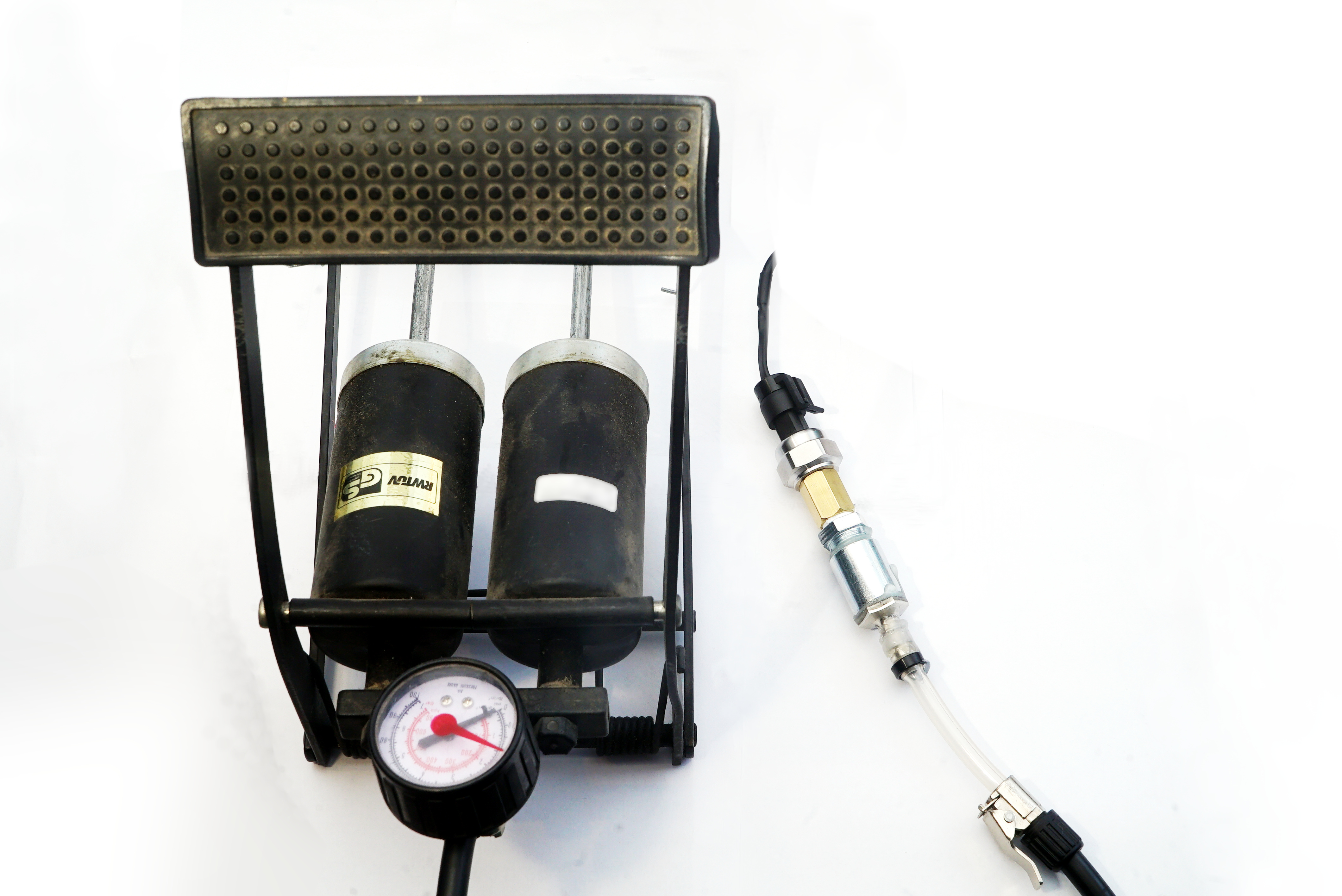
To calibrate the pressure sensor, we recommend using a pedal pump with a very precise manometer. The serial monitor on your computer should print out the current voltage and pressure received by the pressure sensor: you can just use the pedal pump to get exactly 1bar (0.1MPa) and 2bar (0.2Mpa), while writing down the voltage at both pressure values. Then, inside the Dolphin source code, you can just edit the calibration portion of the code writing your voltage readings for each pressure value. For example:
const float Vmin = 0.32;
const float Vmax = 0.55;
const float Pmin = 0.1;
const float Pmax = 0.2;
In this example, at atmospheric pressure (0.1 MPa, the minimum value) the sensor outputted 0.32 V, while at 0.2 MPa (the maximum value tested with the pump) the sensor outputted 0.55 V. Setting these values in the code and uploading it again to Arduino lets Dolphin calculate the linear equation with voltage as the x-axis and pressure as the y-axis. This kind of sensor has, in fact, a linear output. Another option for calibration is to stick a ¼ inch connector at the bottom of a 2-meter PVC pipe, connecting the sensor to it, and just start filling it with water while measuring the level with a tape measure or a meter stick.
To calibrate the Electrical Conductivity probe, you can just follow the procedure on the manufacturer website.
Waterproofing
Silicone shell
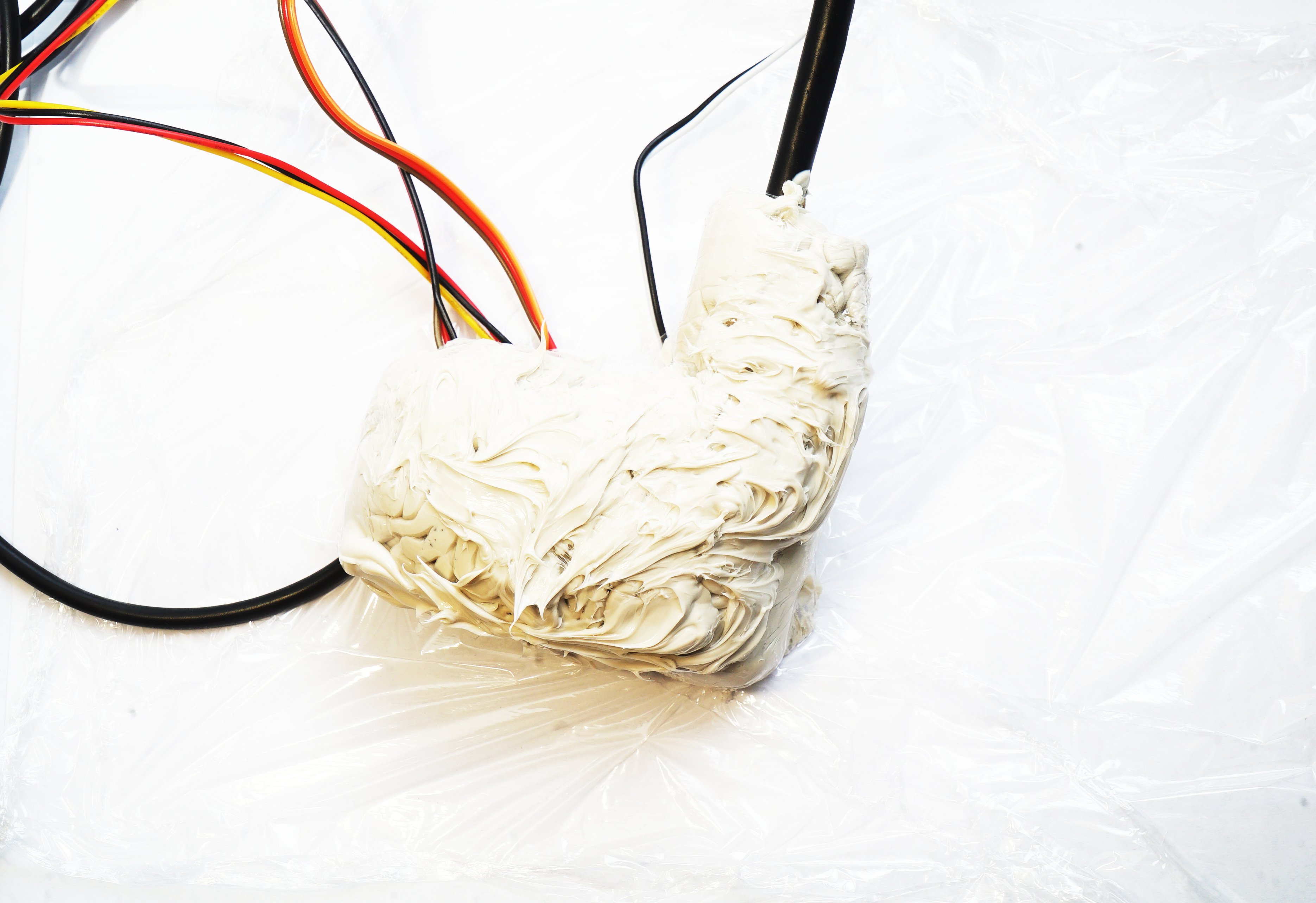
The first option to waterproof Dolphin is to enclose it in a Neutral Cure silicone shell.
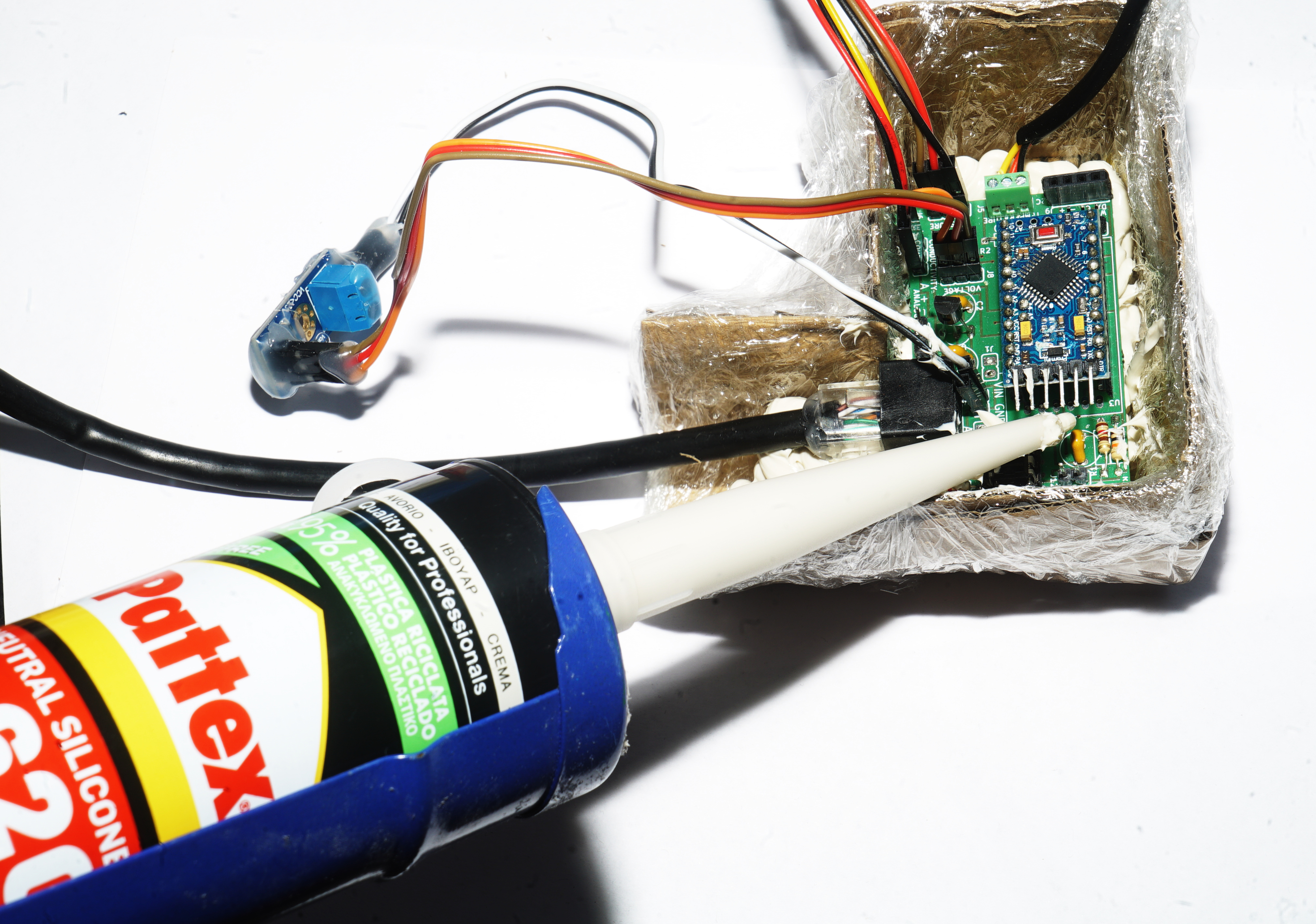
IMPORTANT: the silicone must be neutral cure, because standard silicone products use acids that damage the circuits. We've been using Pattex SL620 for a while, but any other neutral cure silicone should work fine.
This step is not really mandatory: enclosing Dolphin in silicone provides just another layer of shielding, useful against the moisture inside the waterproof plastic enclosure and for little water drops that might enter if the plastic sealing starts to fail.
Internal components
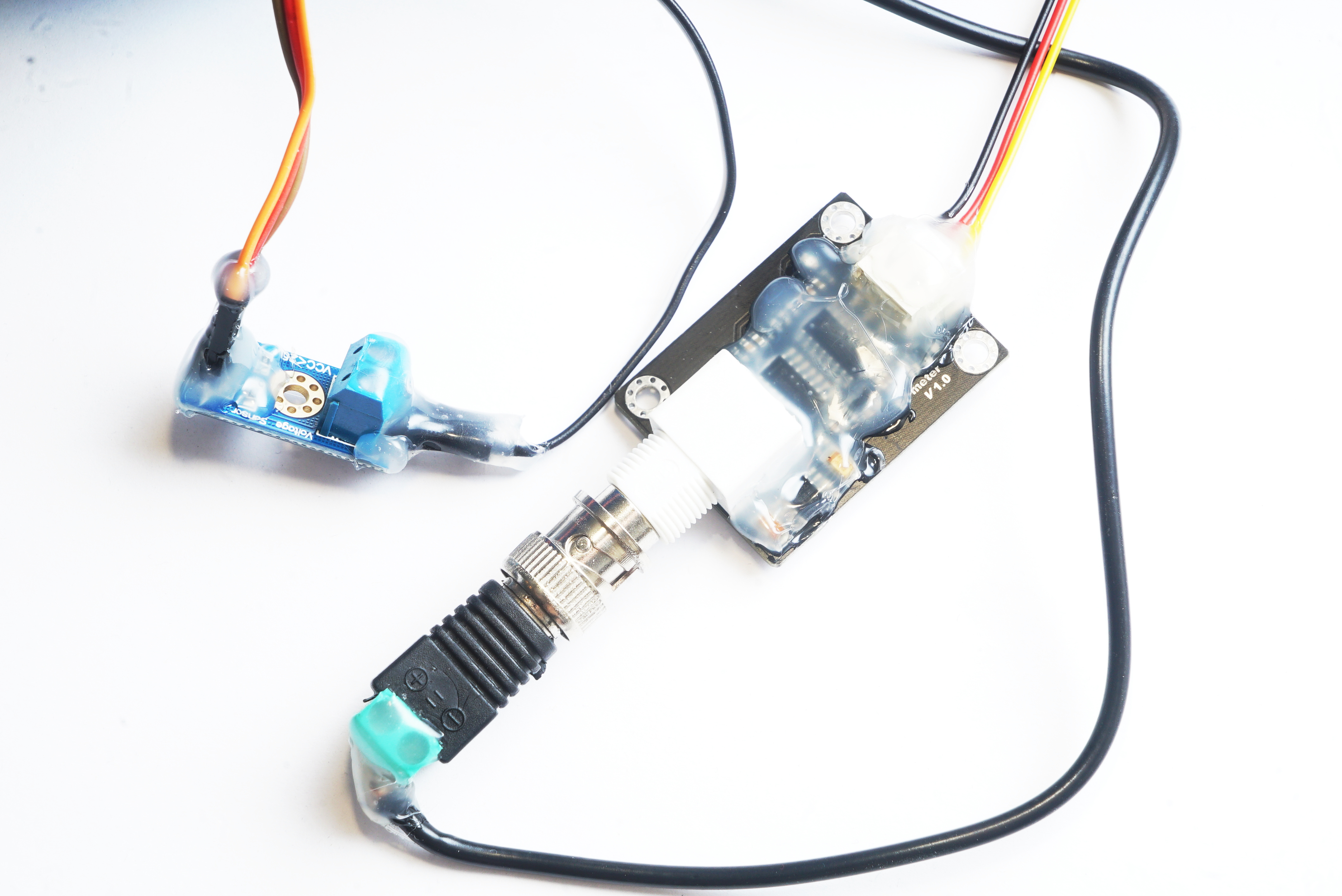
There might be other boards and connectors that will be placed inside the waterproof plastic enclosure. Even if the enclosure is going to protect them, it's a good idea to cover contacts (especially microchips) with hot glue, in particular for everything that wil never be desoldered again in the future.
Plastic enclosure
As a waterproof plastic enclosure, we recommend using a water filter housing: they usually resist up to 80bar, which means almost 70m deep in water.
These housings have a lid with two holes, designed for plumbing tubes.
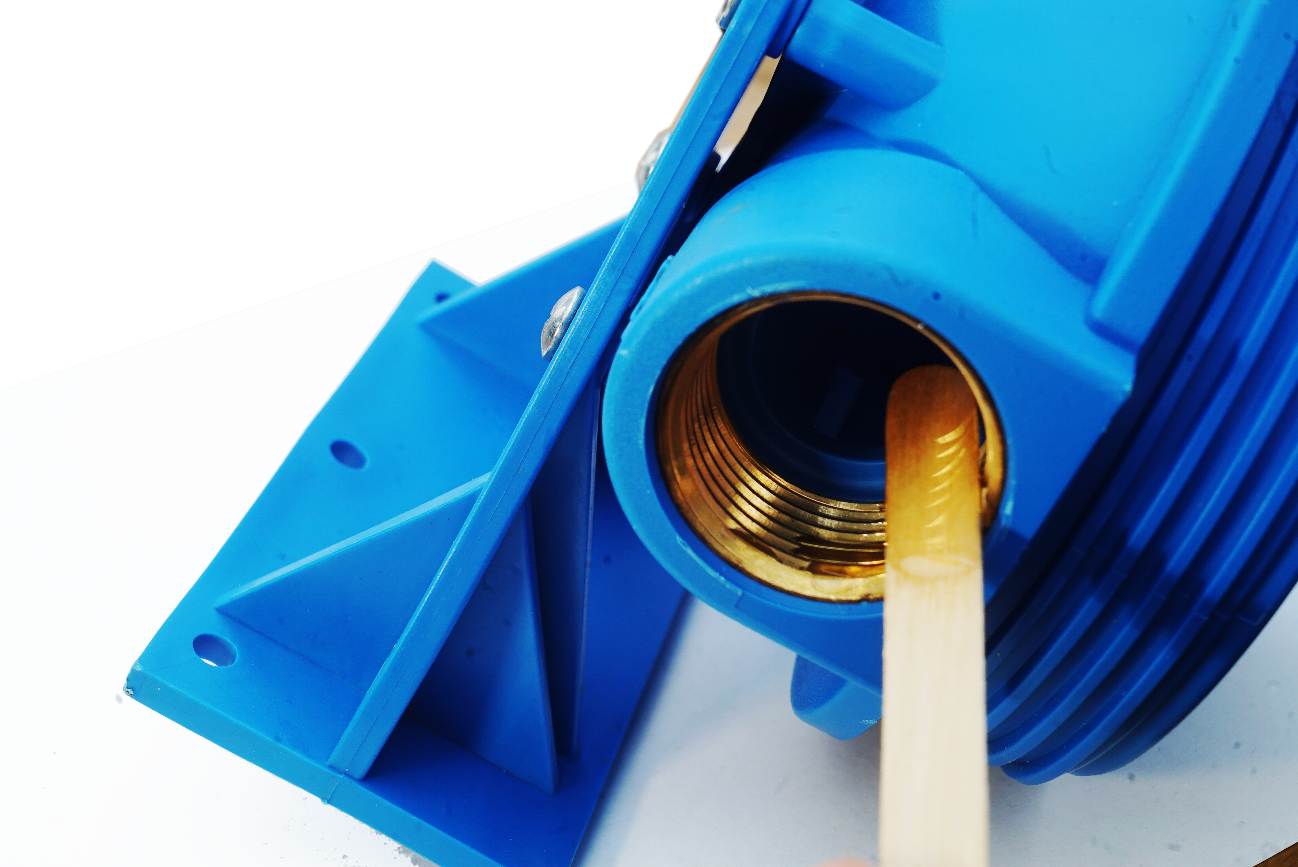
Since they need to be absolutely shut, the first step to perform is placing some epoxy resin on the threads, and inserting the plumbing lids.
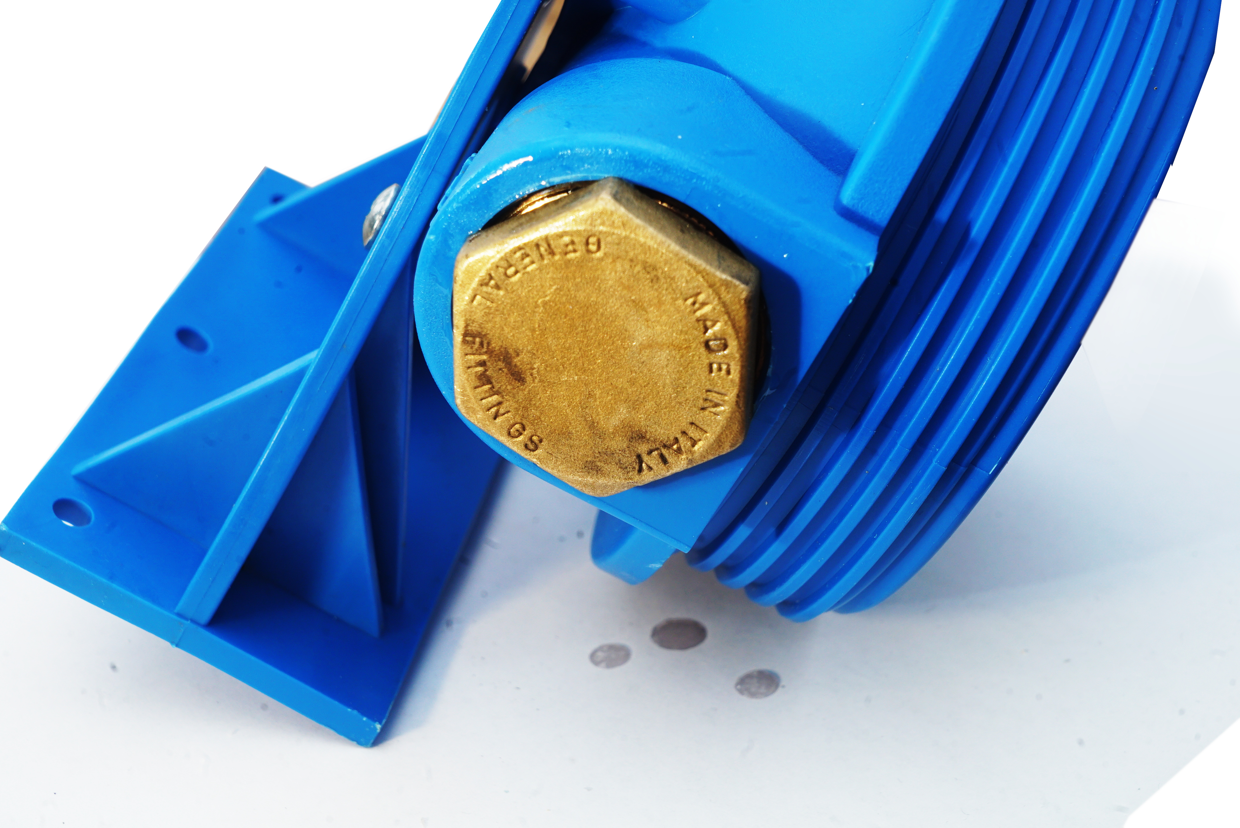
Then, it's also a good idea to drip epoxy resin inside the filter housing lid itself, to make sure every little hole is completely sealed, and there is more resin to resist the external water pressure.
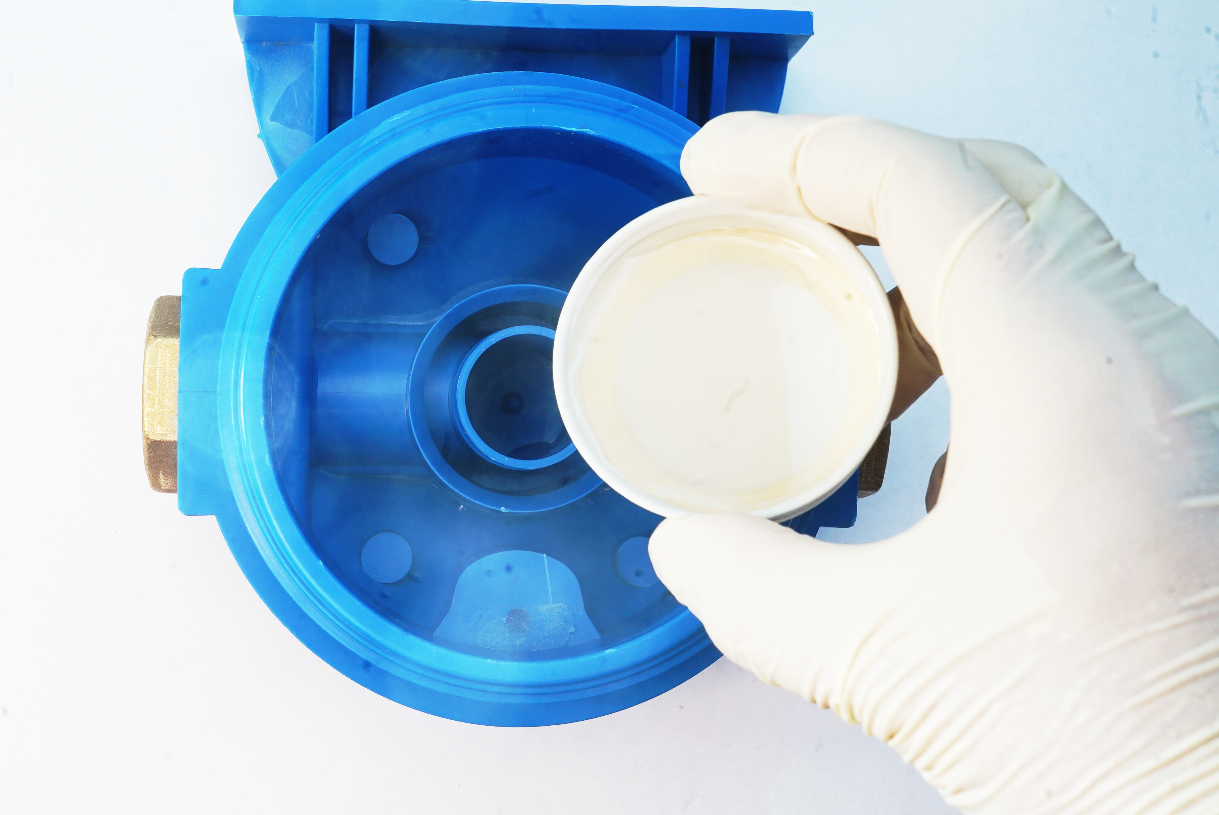
Once the lid has been completely sealed with resin, it's possible to drill holes to the bottom part of the housing. It should be plain, so it's easy to drill holes: there should be a big hole for the pressure sensor (please use the same diameter as the one of your sensor's thread) and two littler for the DS18B20 temperature sensor and the Cat6 ethernet cable. There should also be at least one quite small hole for the conductivity probe, or other external sensors if you have any.
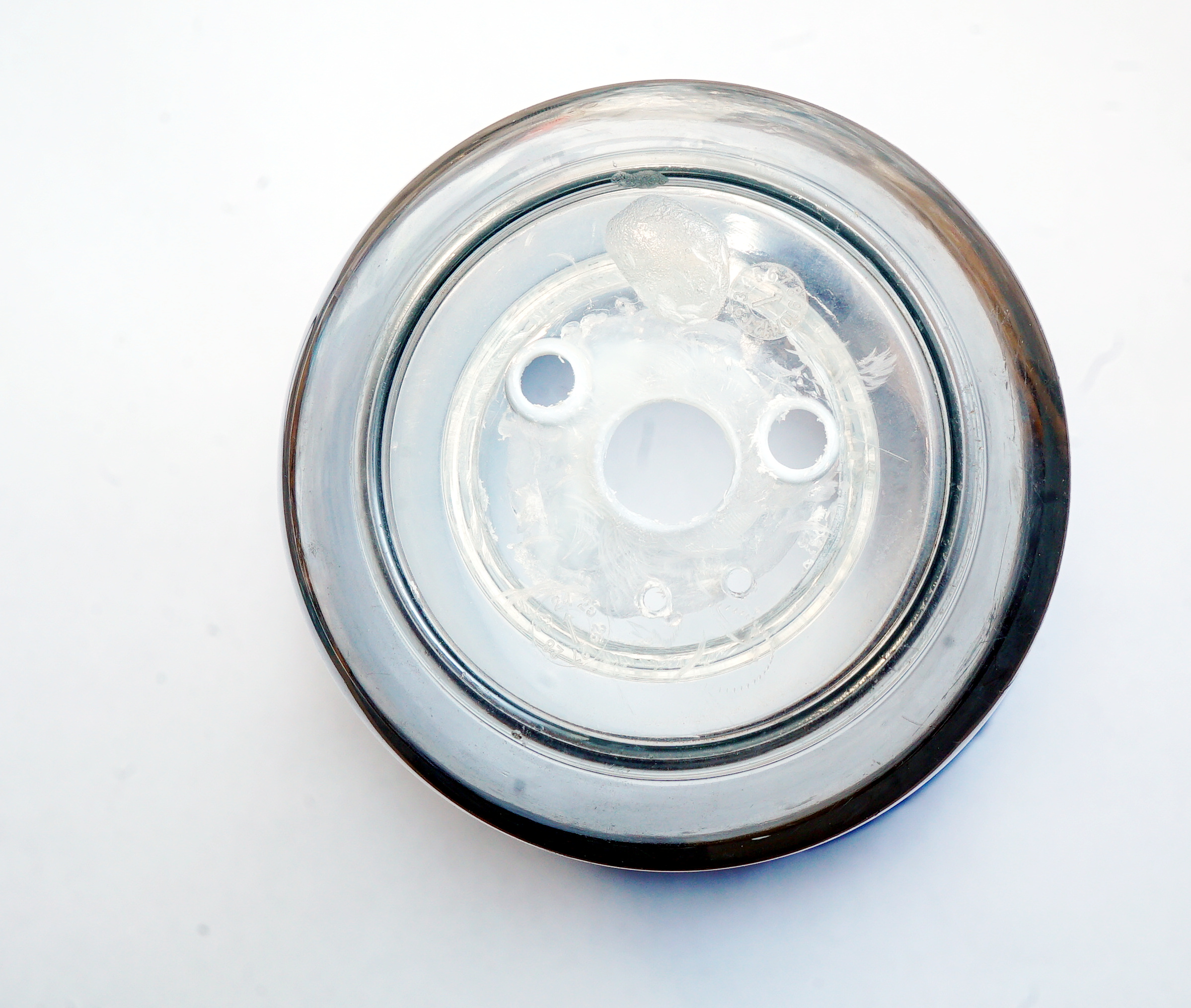
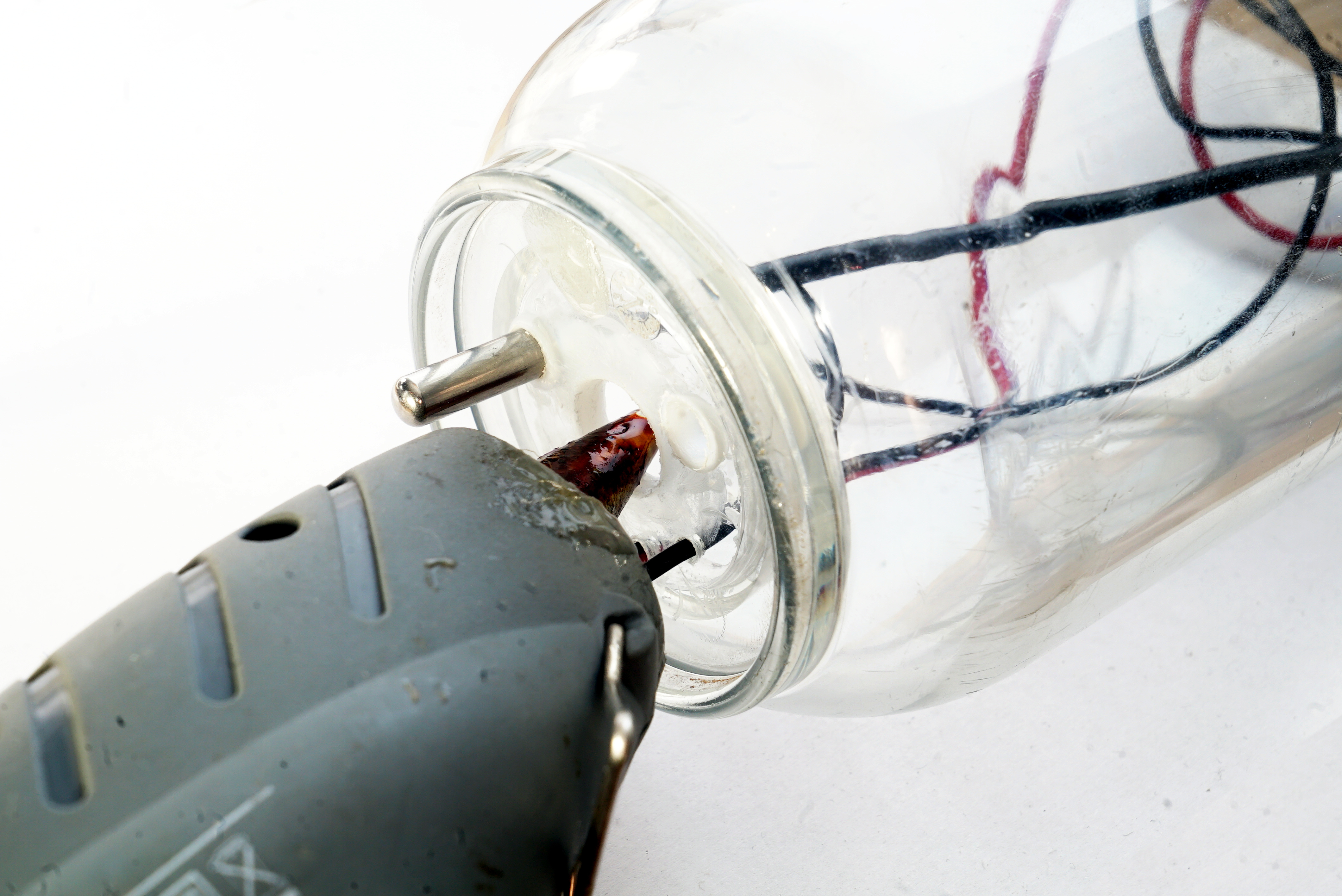
Any hole should be kept as small as possible, so it's easier to hold things in place while sealing everything. In particulare for the pressure sensor, the best option is to place hot glue internally, and stick the sensor in the hole immediately after. This way, the glue will act also as a gasket.
After placing the pressure sensor in the hole and waiting for the hot glue to cool down, it's possible to insert all the other cables or sensors in each hole. It's also recommended to screw a nut on the pressure sensor's thread (once the hot glue is cold), in order to avoid any chance of leakage.
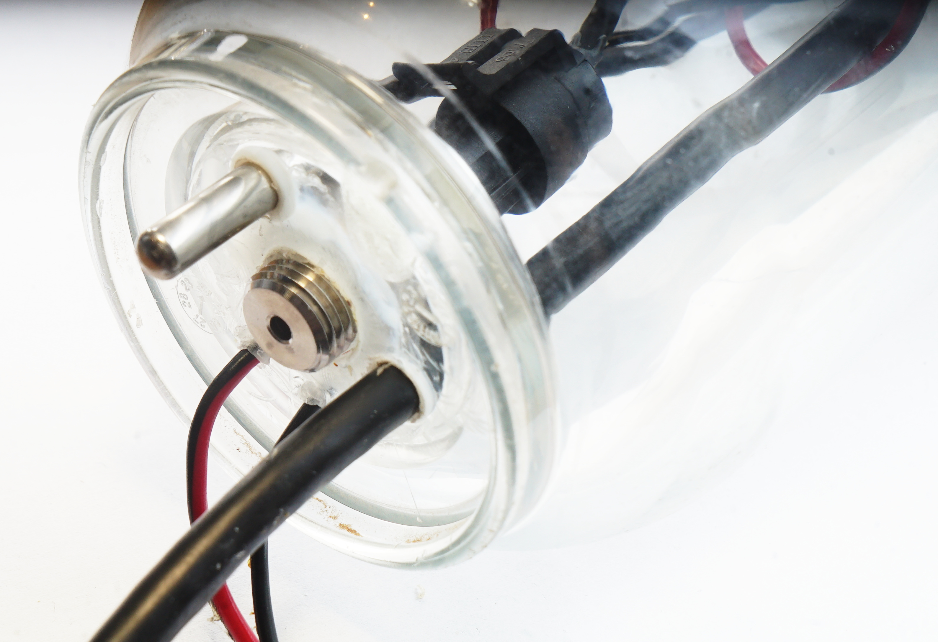
Once everything is in place, it's possible to just pour slow curing epoxy resing on the flat surface, until it reaches the border level, so each hole is completely and definitively sealed.
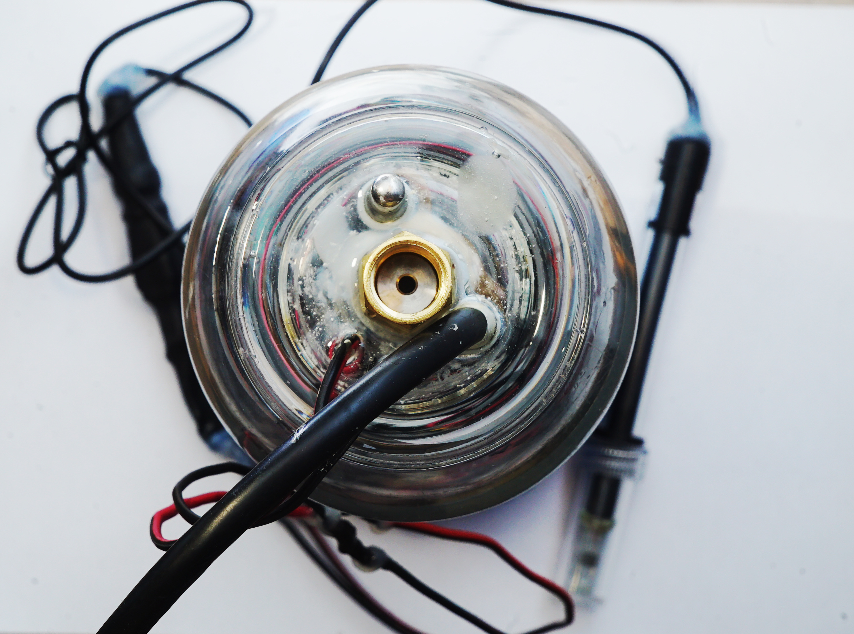
When the epoxy resin has cured, it's possible to simply stuff everything inside the housing and close the lid tightly.
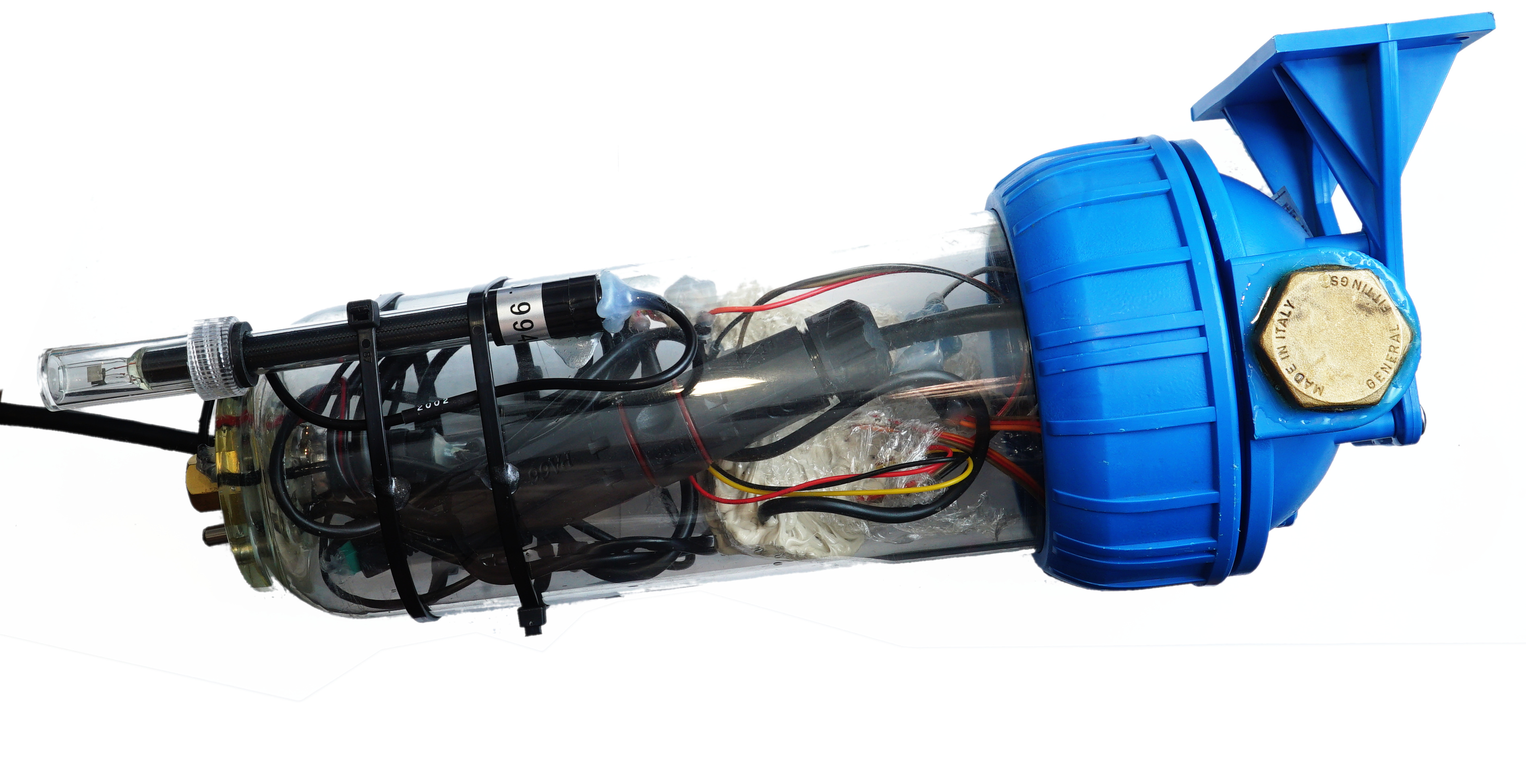
Now Dolphin is ready to be paired up with a Riki and installed inside a cave.
Installing Dolphin
To install Dolphin underwater, it's possible to use the casing screw holes to fix it onto a metal plate, that can then be mounted on the cave wall. It's recommended to fix it firmly, to avoid the chance of it moving during floods (if it moves it could crash and get damaged).
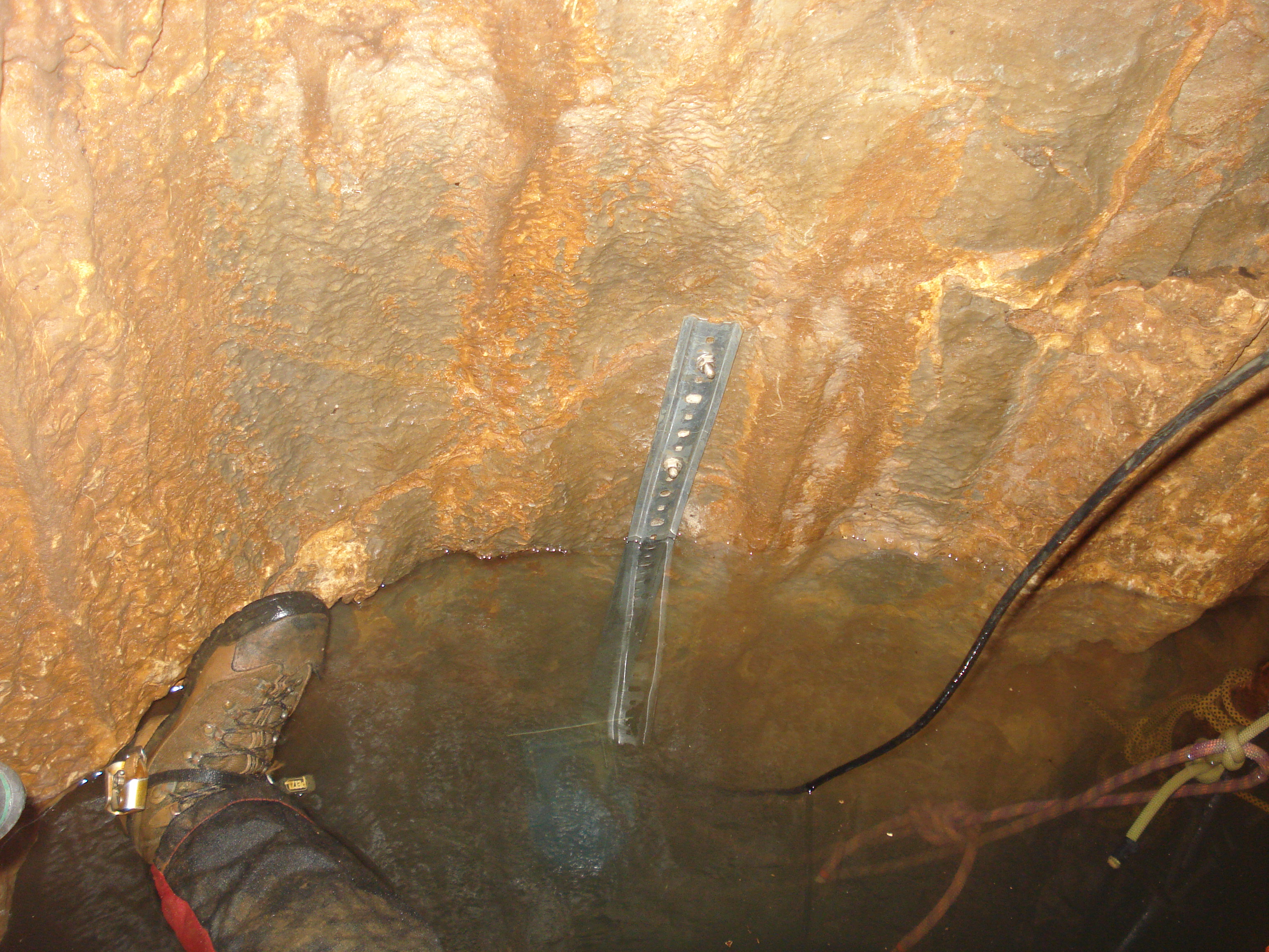
The ethernet cable can be fixed with simple wall mounts, once every 10 or more meters.